
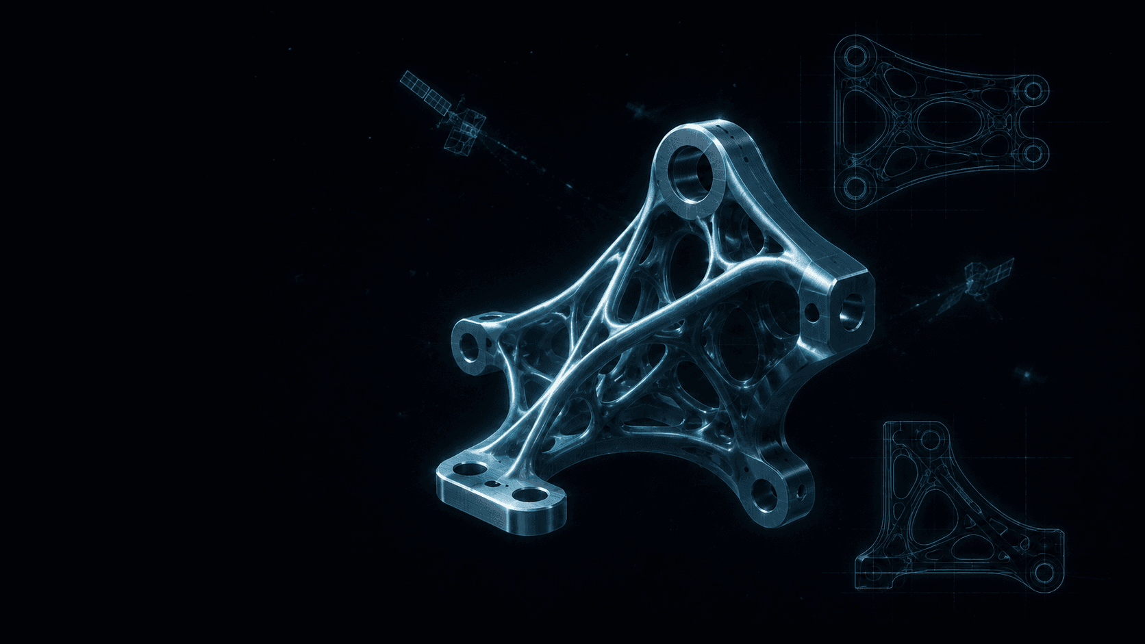
Why aerospace teams pick SolidMake
Aerospace parts live in a constrained design space: strict weight budgets, high safety factors, tight manufacturing envelopes, and stacks of qualification requirements. Traditional CAD workflows spend most of their time re-modelling variants of the same bracket against every packaging change. SolidMake collapses that loop.
You describe the part — in text, with a photo, or with a reference STEP — along with the constraints that actually matter (weight budget, wall thickness, keep-outs, fastener grid). SolidMake proposes parametric geometry that respects them all, and lets you branch, tweak, and regenerate as the packaging evolves. Every output is a clean B-Rep STEP that opens losslessly in CATIA, NX, or SolidWorks.
Parts we generate
- Structural brackets — satellite antenna mounts, avionics rack brackets, sensor pod carriers, wire-harness clamps.
- Housings and enclosures — flight computer enclosures, sealed electronics boxes, RF module cans.
- Fixtures and jigs — ground-support tooling, layup tools, drill jigs, alignment fixtures.
- Topology-optimized panels — internal ribs and access doors where weight is at a premium.
Constraints we respect
- Wall thickness and rib-height limits for additive titanium (Ti-6Al-4V).
- Draft and undercut rules for investment casting and CNC milling.
- Fastener grid, torque-clearance envelopes, and edge-distance rules per NAS/MS/AS conventions.
- Keep-outs from an imported harness, hydraulic run, or neighboring subsystem.
- Weight budget as a hard constraint, not a suggestion.
A representative workflow
A Tier-1 satellite antenna supplier needed to evaluate 18 packaging variants of an antenna mount as the payload configuration was still in flux. Their CAD team typically modeled three variants per week. With SolidMake:
- The lead engineer wrote a brief describing the mount's interface, weight budget, and topology preferences.
- SolidMake produced parametric STEP files for all 18 variants — each respecting wall-thickness, draft, and topology constraints — in under a day.
- The team ran FEA on all 18, downselected to three, and iterated fillets and rib layouts in another afternoon.
Result: 11 days saved, 23% average weight reduction against the incumbent design, and full lineage traceability from spec to STEP.
What you get, ready to use
- STEP AP242 file with feature-tree lineage.
- IGES for legacy tools.
- Machinable B-Rep with hairline-clean edges — no mesh conversion.
- Fillet/chamfer parameters exposed for downstream tuning.
- A one-page manufacturing readiness report: minimum wall, min feature vs. tool radius, planar-face inventory for sheet-metal candidates.