
Why automotive teams pick SolidMake
In EV development, packaging never stops moving. Cell layouts change, cooling loops re-route, harness paths shift, and every one of those changes ripples through a dozen brackets, trays, and covers. Traditional CAD teams spend more time re-modelling than designing. SolidMake takes the constraints once and regenerates.
You capture the intent — cell grid, fastener pattern, cooling channel envelope, crash keep-outs — and the parts follow. Every Monday, before standup, the updated tray, cover, or bracket is waiting. Iteration goes from days to minutes.
Parts we generate
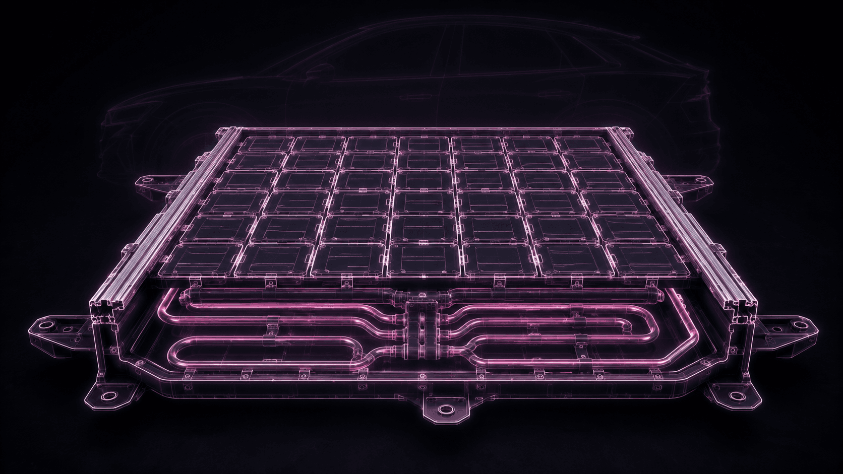
- Battery trays and modules — HV battery pack lower trays, module carriers, cell holders, busbar covers.
- Motor and drivetrain housings — stator housings, gearbox covers, e-axle brackets.
- Body structure brackets — subframe mounts, seat brackets, harness clamps, sensor mounts.
- Cooling components — cold-plate manifolds, coolant routing brackets, radiator supports.
- Interior structure — dash cross-car beam brackets, HVAC ducting supports.
Constraints we respect
- Cell dimensions, module pitch, and cooling-channel keep-outs.
- Crash envelopes and load paths (as keep-outs or minimum-thickness bands).
- Sheet-metal design rules: bend radius, minimum flange, hole-to-edge distance.
- Fastener grid with DIN/ISO/SAE torque-clearance envelopes.
- Weld-access clearance, joint fitup gaps, and self-piercing rivet zones.
- Corrosion-protection features (drain holes, e-coat access, gasket lands).
A representative workflow
An EV startup was rebuilding the battery tray from scratch every sprint as cell-supplier selection kept flipping. Their mech-eng lead brought the cell-layout spreadsheet, cooling channel definition, and floor mount points to SolidMake:
- The tray became a parameterized model — cell rows, cooling geometry, and mount points all named variables.
- When the cell size changed, only the parameters changed. Regenerating produced a new tray, new cover, and new module carriers, all consistent, in under three minutes.
- The team stopped rebuilding and started iterating: rib layouts, cooling manifold routing, seal-groove tuning.
Result: iterations went from once a sprint to five times a week. 32 CAD-engineer hours per week freed up. First-prototype tooling delivered in 3 days instead of 9.
What you get, ready to use
- STEP AP242 and IGES with parametric feature history preserved.
- DXF unfolded flat patterns for sheet-metal parts (with bend-line annotations).
- A machinability report: min wall, min feature vs. tool radius, undercut inventory.
- Named parameters exposed so downstream engineers can nudge dimensions without opening a modelling tool.