
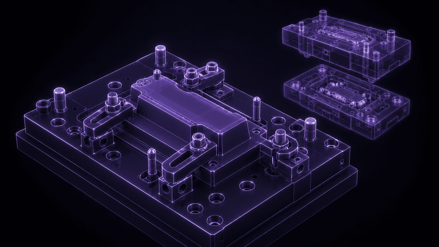
Why tooling teams pick SolidMake
Tooling engineering is derivative work by nature: every fixture, jig, and mold insert is a function of a part file that already exists. What varies is the tooling shop's own rules — reference planes, clamp locations, sacrificial features, dowel-pin patterns, insert-block conventions. Traditional CAD makes you re-derive the tooling geometry by hand for every part that comes through the door. SolidMake takes the part and the rules, and generates the tooling.
What we generate from an existing part file
- Assembly and inspection fixtures — locator plates, hold-down clamps, GD&T datum tooling.
- Drill and mill jigs — bushings, pocket templates, port-drill fixtures.
- Injection-mold cores and cavities — with parting-line generation and shrinkage compensation.
- Progressive-die and stamping tooling — punch-and-die plates, strip layouts.
- Wire-EDM and sinker-EDM electrodes — with erosion allowance and shank interface.
- Custom cutting tools — form tools, threading tools, custom broaches.
Constraints we respect
- Your tooling standards library (base plates, subplates, dowel patterns, T-slot grids).
- Datum and locator conventions (typically 3-2-1) and the specific reference features on the part.
- Draft, shrinkage, and cooling-channel rules for mold inserts.
- Access clearance for the actual manufacturing operation (drill length, tool holder shank, hand-clamp reach).
- Compatibility with your shop's floor tooling (CNC bed size, machine envelopes, WCS zeroing conventions).
A representative workflow
A contract-manufacturing shop was on a tight deadline to bring 12 new customer parts into production. Each part needed a full tooling set: locator fixture, machining fixture, inspection fixture, sometimes a soft-jaw insert. Their tooling engineer was quoting eight weeks. With SolidMake:
- The tooling engineer loaded the shop's standard base-plate library and subplate library as templates.
- Each customer part was fed through the tooling generator with the required workflow (mill, inspect, ship).
- SolidMake produced tooling STEPs that referenced the shop's own subplates, matched to the specific part geometry.
- The engineer reviewed each output, tweaked the few that needed non-standard clamp routing, and released to CAM.
Result: the tooling set of 36 fixtures was delivered in nine days instead of eight weeks. The tooling engineer's next hire was a technician, not another CAD modeler.
What you get, ready to use
- Tooling assembly as a STEP file, referencing your standard components as external assemblies.
- BOM with your standard part numbers where possible.
- Clamping-and-locator strategy diagram.
- Setup sheet drafts (fixture ID, clamp torques, dowel pattern) ready for shop-floor review.