
Why industrial teams pick SolidMake
Industrial machinery has a long tail of small mechanical parts that don't justify a dedicated CAD engineer but still need production-quality geometry: a custom valve adapter, a machine-specific jig, a bracket that carries a sensor onto a proprietary drive shaft. These parts stack up. Every one is a small job that costs an outsized fraction of your CAD budget.
SolidMake handles the tail. You describe the part, its interface to the machine, and the manufacturing route. Out comes a machinable STEP, a DXF for any planar face, and a manufacturing report — often within minutes.
Parts we generate
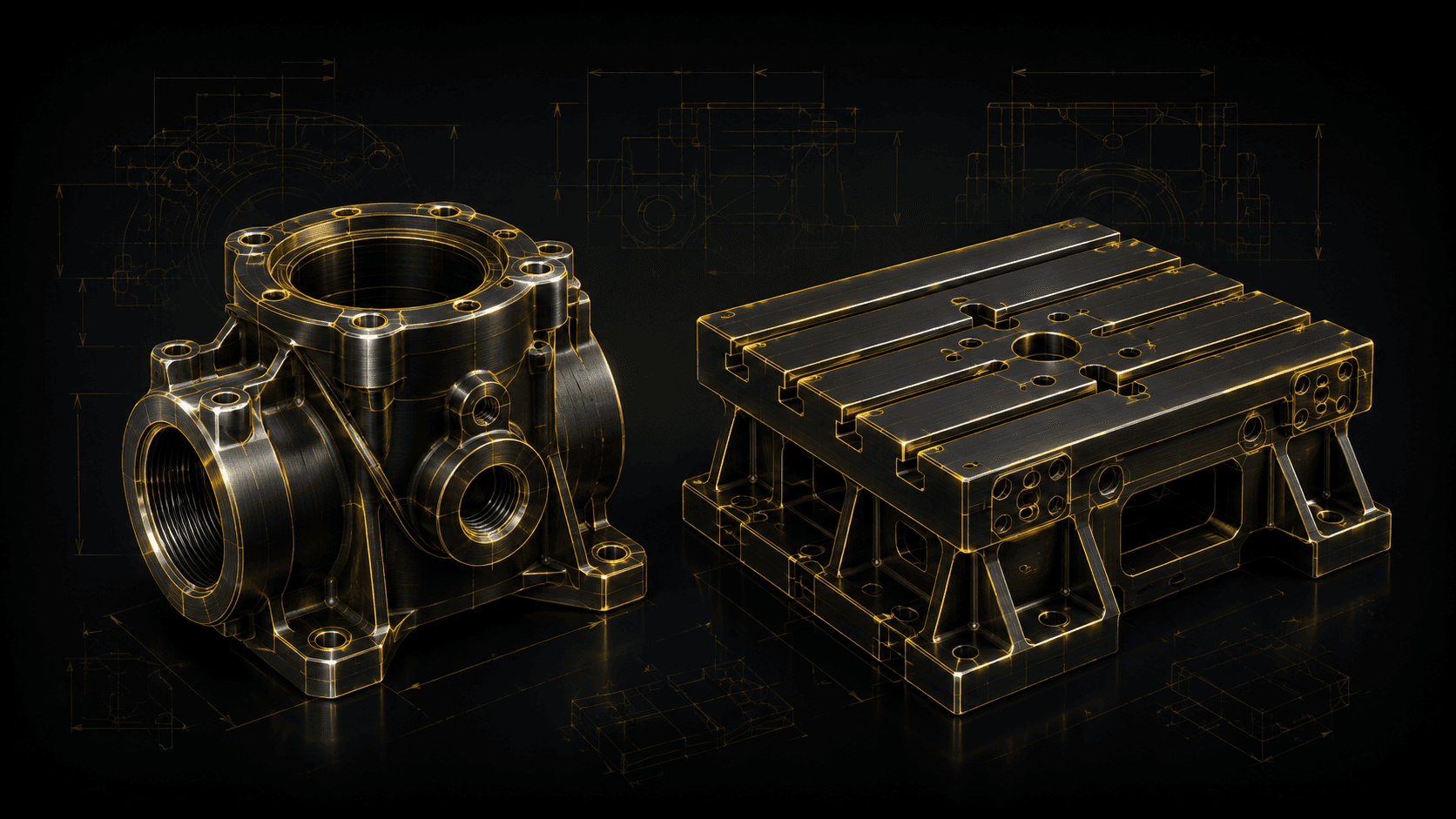
- Fluid handling — pump housings, custom valve bodies, manifold plates, gasket flanges.
- Machine frames and fixtures — welded steel frames, jig plates, tool holders, alignment fixtures.
- Sensor and actuator brackets — encoder mounts, proximity-switch tabs, linear-actuator carriers.
- Guarding and enclosures — sheet-metal safety guards, control-panel housings, cable-tray brackets.
- Wear items — replaceable bushings, guide rails, wear plates, dressing tools.
Constraints we respect
- CNC-machining constraints: min internal radius vs. tool (default 1 mm), pocket depth vs. tool length, tool-access clearance.
- Sheet-metal rules: bend radius per material, min flange, min hole-to-edge, K-factor.
- Weld-access geometry: fitup gaps, weld-bead clearance, backpurge access.
- Bolt-and-nut wrench clearance (imperial and metric fastener envelopes).
- Fatigue-loaded fillet-radius minimums where load path is critical.
- Sealing surface finish call-outs (Ra targets) on gasket lands and O-ring grooves.
A representative workflow
A packaging-machine OEM was rolling out a new bottle format across a customer's plant. The change required 47 small mechanical modifications: brackets, guides, feed-star adapters, sensor mounts. Their senior CAD designer would have needed six weeks. With SolidMake:
- Each modification became a short brief with a reference photo of the existing part and a description of the change.
- SolidMake proposed geometry for all 47 in the first afternoon. About 40 were accepted as-is; 7 were iterated interactively.
- The team sent STEPs to their machine shop and DXFs to their sheet-metal supplier the same day.
Result: six weeks of senior CAD work reduced to four days. The senior designer spent that week designing the next machine platform instead.
What you get, ready to use
- STEP AP242 + IGES for CAM.
- DXF for any planar-dominant face (laser/waterjet/plasma-ready).
- G-code hints for common tool families where SolidMake can infer safe strategies.
- Full BOM with hardware and material call-outs.
- Manufacturing readiness report with tool-access, min-radius, and sheet-metal-feasibility checks.